|
Van used
coaxial delay lines in his two-element phased array, and
some users still use delay lines with good results.
However, we must always remember this extremely important
fact about delay lines…..
The phase shift of a transmission line is only equal to its
electrical length when the line is terminated into its
characteristic impedance.
What is the
statistical probability that the feedpoint impedance at
either element of a two-element phased array will be the
characteristic impedance of coax, 50 + j0? I am inclined to
think that your chances of winning the lottery is better
than the chance of finding a purely resistive 50 ohm load at
either element of a two-element phased array. Delay line
proponents assume they are cutting a line of a particular
electrical length, but in practice the electrical length of
their line depends upon the impedance of the load it is
terminated in.
Another
compromise of using delay lines is that the delay line has
no flexibility to perform impedance matching that will cause
equal current magnitudes to flow into each element. Equal
currents in each element are required for maximum
front-to-back. Unfortunately, delay lines fall far short of
providing the ability to simultaneously achieve optimal
phase shift and optimal impedance matching that is required
for equal currents in each element.
The
variable LC phasing network, however, does give the
flexibility of achieving optimal phase shift and optimal
impedance matching for optimal current distribution.
Figure 1
below is a sketch of the simple two-component LC phasing
network that I used for years with the phased array.
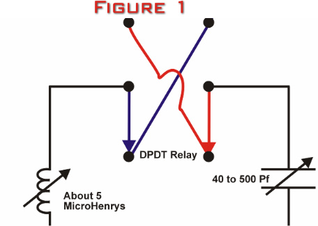
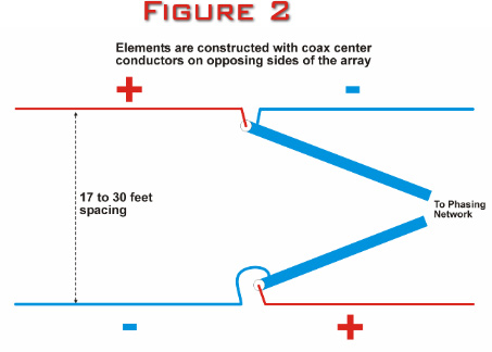
Figure 2
below illustrates the feedline connections to the elements.
Please notice there is a 180 degree phase reversal by
putting the shields on opposite sides of the array. Some
users get best results without transposing the feedlines,
but I have always found the nulls easier to identify with
the feedlines transposed.
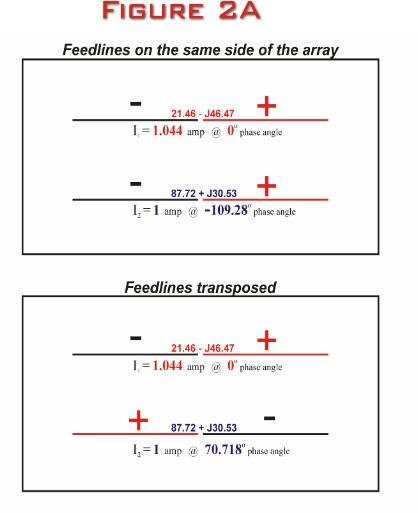
Figure
2A below illustrates both the transposed and
non-transposed configurations of the array, along with the
feedpoint impedances, current amplitudes and current phase
relationships. Please notice that all parameters are
identical for both configurations at maximum front-to-back,
except for the current phase relationships.
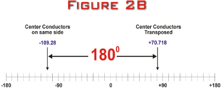
Figure
2B below illustrates why the two configurations are
really identical. The difference in phase relationship
between the transposed and non-transposed configurations is
+70.718 – (-109.28) degrees, which is equal to 180 degrees,
the exact additional phase shift created by transposing the
feedlines. The reason I transpose my feedlines is that it
is easier to create the +70 degrees of phase shift with the
LC network for the transposed configuration than it is to
create the –109 degrees with the LC network for the
non-transposed configuration.
When
adjusting the array for maximum front-to-back, the roller
coil and variable capacitor are adjusted for a signal null.
Although this works well, the roller coil changes reactance
relatively slowly as compared to sweeping a variable
capacitor through its range of reactance. This makes
identifying the deepest part of the signal null difficult as
the roller inductor is turned back and forth. After twenty
years of using the two-component LC network, it finally
dawned on me that the addition of a variable capacitor in
series with the roller coil would make it much easier to
identify the null in the inductive leg by utilizing more
coil (inductive reactance) than necessary, and then adding a
series variable capacitor (capacitive reactance). By tuning
the variable capacitor in series with the roller coil, I
could sweep rapidly through a wide range of net
inductive reactance values to identify the maximum
front-to-back null. By choosing a value of the fixed
inductance carefully, the values of the variable capacitor
can be determined that will allow the net reactance of the
inductive leg to remain inductive over the majority of the
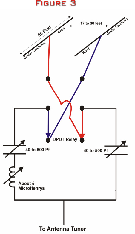
capacitive values. The great advantage of this
three-component LC network is tuning speed in the inductive
leg. And so was born the three- component L/C phasing
network, illustrated by the sketch in Figure 3 below.
The
three-component L/C phasing network (Photograph in Figure
4 below) is extremely quick to find the null and is very
precise. Amateur radio operators are already accustomed to
using two hands with the tune and load knobs to adjust their
power amplifiers, so the neural pathways are already
established to adjust the two capacitors of the
three-component LC phasing network to identify maximum
front-to-back.
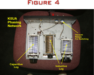
Figure 5
below shows the reactance of the capacitor in the capacitive
leg as it is swept through it’s range of values.
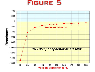
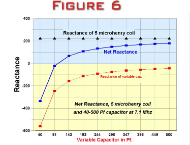
Figure 6
below illustrates the net reactance of the series
coil/capacitor combination in the inductive leg as the
capacitor is swept though it’s range of values. Please note
that the two capacitors must be isolated above ground on
ceramic standoff insulators. The roller coil is typically
isolated above ground by its housing, but if in doubt, put
it on ceramic standoff insulators also. I used vacuum
relays for the switching, but a conventional DPDT RF relay
works just as well. I have even used a Radio Shack knife
switch for the switching and it also worked well.
When
sifting through the antenna literature, one immediately
recognizes the similarity of this antenna to the famous
"8JK" by John Kraus, W8JK. The “8JK” is bi-directional
because of the 180 degree phasing between its elements. The
two-element phased array as described in these pages is
unidirectional and has a typical horizontal pattern very
much like the parasitic yagi. The phase relationship
between the elements for maximum cancellation is somewhere
between 115 to 150 degrees, depending upon the spacing
between the elements, the height above ground, and the
arrival angle of the incoming signal.
|